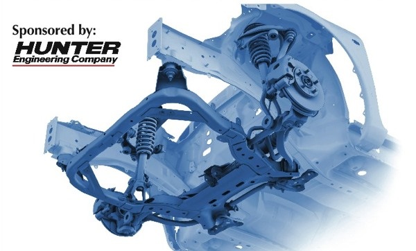
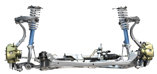
2007 Ford Fusion Front Suspension Diagram
Features
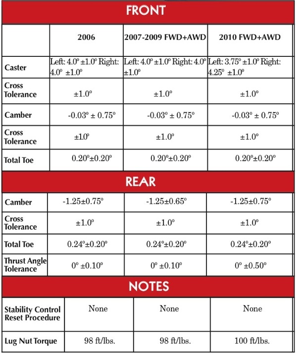
Alignment and Suspension Specs: Ford Fusion 2006-2010
In 2006 when Ford introduced the Fusion, many could not help but to compare it to the third- and fourth-generation Taurus models. The previous generation had a reputation for broken springs and tire shredding bushing problems. The 2006-2010 Fusion is a different story.
 AWD and Hybrid models do not differ significantly from the FWD models, and the same is true for 4-cylinder and V6 models. One of the only differences in AWD model specs is the rear ride height.
Click Here to Read More
If you get one of these vehicles in your shop, you need to be aware of a few things at write-up that could turn a "menu priced" alignment into a very expensive procedure. Be aware, to adjusting the camber or caster in the front requires replacement of the upper ball joint with an aftermarket adjustable unit. Also, the caster can be adjusted with new upper "plus or minus" control arm from Ford.
 Front Suspension
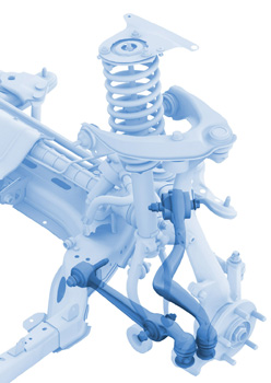
The front suspension on the Fusion uses a double ball joint arrangement on the lower control arms. If one of the links or joints is damaged, it can create steering problems like poor returnability and inconsistent steering feel.
There is no built-in camber or caster adjustment for the front suspension. Adjusting these angles requires an adjustable ball joint for the upper control arm. The adjustable aftermarket ball joint is easy to install and will give ±1.0º of camber or caster. Some adjustable ball joints can give as much as ±1.5º.
 The caster can also be altered by changing the upper control arm. Ford has released four different control arm part numbers (two for each side) that alter the caster by ±0.4º depending on the control arm ordered. This is not a "standard adjustment" but should be used as a last resort if the vehicle can not be brought to within specifications.
When you reinstall the upper control arm, it is critical to align the bushings in the body bracket. Failure to do so will result in noise and vibration. When installing the bolts that attach the control arm to the vehicle, do not tighten fully. To align the hole in the upper arm with the hole in the body bracket, insert a 6.35mm (0.25 inch) drill bit through both holes. Tighten the upper arm-to-body bolts to 35 ft./lbs. and remove the drill bit.
Inspection of the suspension components is necessary before performing an alignment. Replacing damaged suspension components may save time and be more profitable as opposed to installing adjustable components. Take time to look at the alignment readings and compare them side to side. While a shifted or damaged cradle may be impossible to diagnose with the naked eye, the camber and caster angles can be more conclusive.
Rear Suspension
The rear suspension is adjustable without any parts or kits. The toe is adjustable using a toe link. Camber is adjustable by an eccentric bolt in the lower control arm. There have not been any reports of sagging or broken rear springs like on the Taurus model it replaced.

Ride Height
Jounce the car's suspension several times, making sure to pull up and release several times.
In the front, the first measurement is taken from the center of the inboard lower control arm bolt to the ground. Next, measure the distance from the ground to the underside of the control arm directly under the strut. Subtract the second measurement from the first; this will give you the height specification for that side. Average the the measurements for both sides. On all models including AWD, the distance should be 2-11/16" (68mm) ± 3/4" (19mm).
In the rear, the first measurement is taken from the center of the inboard lower control bolt to the ground. Next, measure the distance from the ground to the center of the bolt of the outboard pivot bolt. Subtract the second measurement from the first and this will give you the height specification. Average the the measurements for both sides. The specification for the rear for FWD models is 2-9/16" (65mm). On AWD models, the specification is 2-1/32" (52mm). On both models, if it is below specification by 7/8" (19mm), Check for damaged springs or suspension components.
Steering Position Sensor
Stability control was optional in 2009 and standard in 2010. If a toe adjustment was made, it is not required to calibrate the steering.
Related
Brake Job: Ford Fusion
In the short time the Fusion and its cousins have been on the road, there have not been any recalls or TSBs issued for the brake system. Customer and field reports are positive and there are very few reports for brake noise. More
Alignment & Suspension Specs: 2003-2007 Cadillac CTS
The first-generation Cadillac CTS was introduced in 2003 and ended production in the 2007 model year. The Cadillac CTS was built on GM's rear-wheel drive Sigma platform. The CTS for years 2003-2007 came with two suspension packages – standard and sport. The packages have two different alignment spe… More
Tech Tip: New Caster/Camber Adjustments for Old Ford Ranger
The cam bolt and nut kit that was used for adjusting caster and camber on all torsion bar and coil spring front suspensions prior to 2004 has been discontinued. Now, if the caster and camber settings need to be adjusted, a washer must be installed. The right-hand upper control arm design changed from… More
How can centering a steering wheel during an alignment cause a vehicle to turn a blind eye? In the past two years we have seen more vehicles on the market with stability management and adaptive cruise control. If a vehicle with one of these systems comes into your shop More

Source: https://www.techshopmag.com/alignment-and-suspension-specs-ford-fusion-2006-2010/
Posted by: margotmargotragere0268815.blogspot.com
Post a Comment for "2007 Ford Fusion Front Suspension Diagram"